
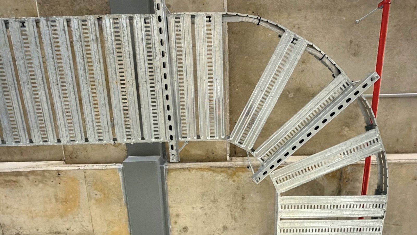
Need to know how to bend cable tray to 90 degrees? This quick guide for Australian electricians shows how to mark, cut and form T3 or T5 cable tray, then secure the bend with a matching radius plate. Use this method when a straight run cannot follow the required route around columns, walls, plant or other services.
Watch: How to Bend Cable Tray to 90 Degrees
What You Need to Make the Bend
Check that you have the required tray, components, tools and PPE before starting.
Parts Featured in This Guide


How to Bend Cable Tray to 90 Degrees
1 Confirm the Route and Bend Position
Check the required direction, available clearance and support arrangement before marking the tray. Confirm that the finished route will allow the installed cables to maintain their specified minimum bend radius.
Always check the cable manufacturer’s data and project specification before pulling cables.
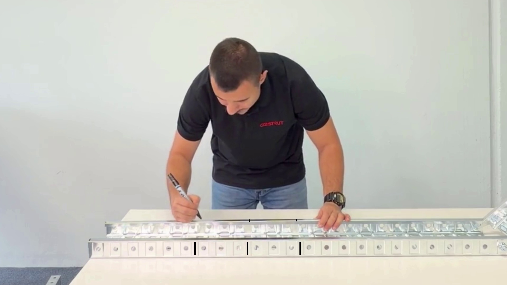
2 Mark Three Bend Points
Use a marker to identify three cutting positions along the side wall that will be fully cut. Mark three relief-notches on the opposite wall.
Keep the marks aligned across the tray so the bend forms consistently. Don’t cut the notches too far into the tray wall; the outer edge of the wall must remain intact. With T3 or T5 cable tray, the pre-punched openings in the tray base allow the bend to form without cutting across the base.
Safety Before Cutting Cable Tray
Only trained and authorised people should cut cable tray. Follow the site risk assessment, SWMS, workplace procedures and tool instructions.
- Secure the tray before cutting.
- Inspect the grinder and use the correct disc and guard.
- Wear the required PPE, including suitable eye and hearing protection.
- Keep sparks, hands and other people clear of the cutting area.
See SafeWork NSW’s guidance on guards and discs on angle grinders. This guide does not replace site requirements or manufacturer instructions.
3 Make Three Full Cuts Through One Side Wall
At each marked position on one side of the tray, cut through the full height of the cable-tray wall down to the base.
Control the tool carefully and avoid cutting across the tray base. The aim is to release one wall at three points while keeping the tray base intact.

4 Cut Three Small Relief Notches in the Opposite Wall
On the other side of the tray, make one small relief notch in the cable wall – opposite each full cut. These notches allow the opposite wall to bend as the tray is formed.
Do not cut this second wall through completely. The method uses three full-height cuts on one wall and three small notches on the other.

5 Deburr and Inspect the Cut Edges
Remove burrs and sharp projections using an appropriate method. Check that the tray base has not been unintentionally cut and that each relief notch is clean enough to let the tray move without tearing.
Do not leave an edge that could damage a cable or injure someone during installation and maintenance.
6 Form the Tray Gradually to 90 Degrees
With the cuts completed, bend the tray slowly until it reaches the required 90° direction. Form the three bend points so the direction change develops as a curve rather than one sharp fold.
Check the angle and route as you work. Avoid repeatedly bending the steel backwards and forwards.
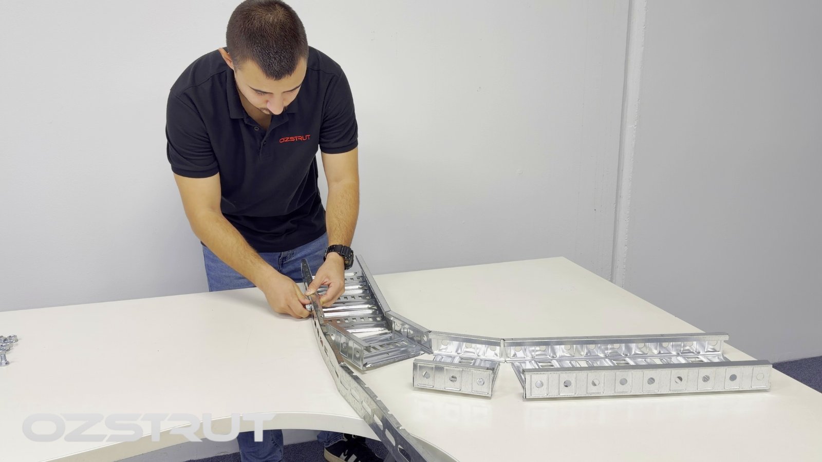
7 Fit the Correct Radius Plate
Select the radius plate that matches the tray type: use a T3 radius plate for T3 tray and a T5 radius plate for T5 tray.
Position the plate so it begins before the first bend, as shown in the tutorial. Align it with the tray and insert the required cable tray nuts and bolts through the available fixing points. The oval holes in the tray wall are for the cable tray nuts and bolts to be installed.
8 Tighten and Complete the Final Check
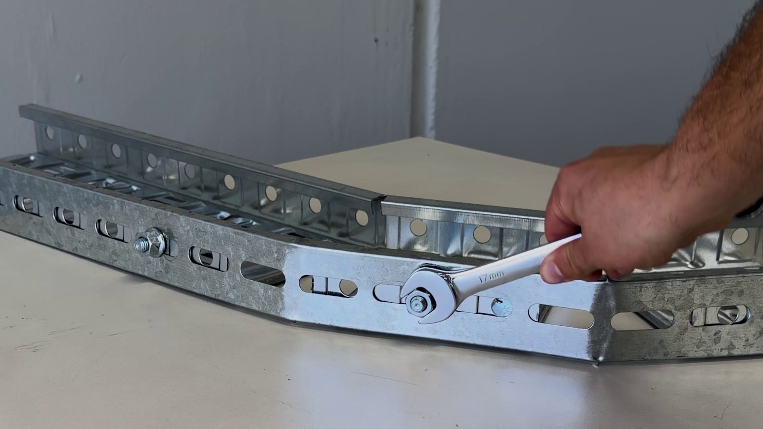
Tighten the cable tray nuts and bolts with a spanner. Confirm that the bend follows the intended route, the radius plate is correctly seated, all specified fasteners are secure and no uncontrolled splits, burrs or sharp edges remain.
Also confirm that tray surfaces will not damage the cable, the completed bend is supported in accordance with the project design and the available radius suits the cables being installed. The tray can then be installed and inspected before the cable is installed inside it.
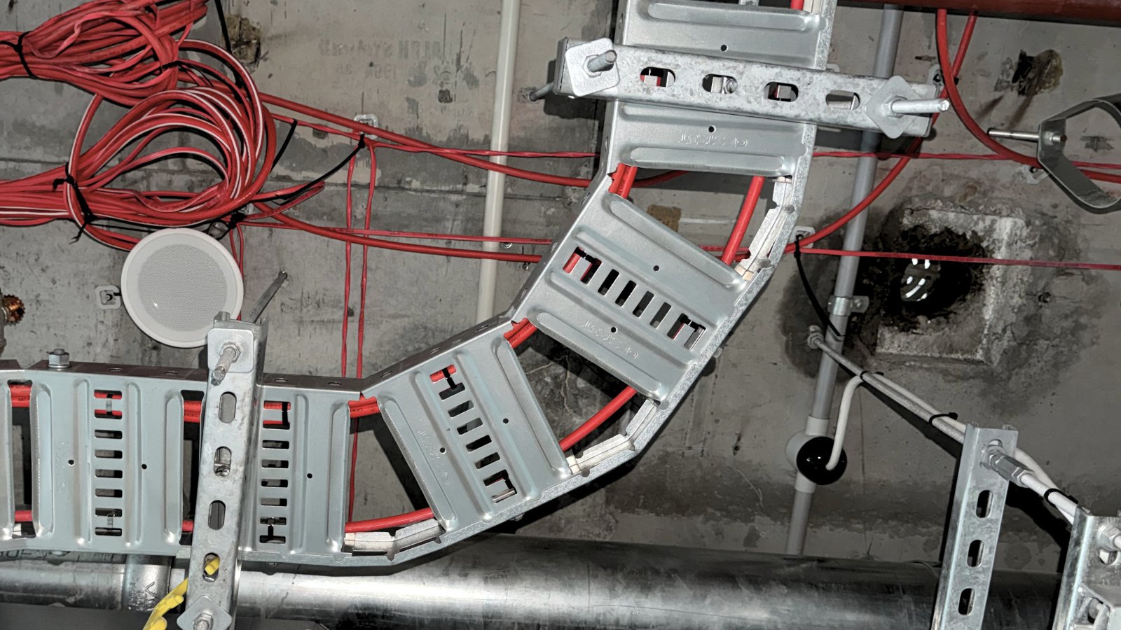
How the Finished Cable Tray Bend Looks When Installed
Once installed, the completed bend should create a smooth and supported 90° change in direction. The matching radius plate follows the formed section, while the cable tray nuts and bolts hold the assembly securely in position.
Before cables are pulled, check that the bend follows the intended route, the tray is supported in accordance with the project design and all cable-bearing surfaces are free from burrs or sharp edges. The available bend radius must also suit the cables being installed.
Common Cable Tray Bending Mistakes
Cutting Both Walls Completely
Use three full cuts on one wall and only three small relief notches on the opposite wall.
Cutting Across the Tray Base
The base remains intact during this method. Keep each full-height cut within the selected wall.
Using the Wrong Radius Plate
Use the radius plate made for the T3 or T5 profile and the specified finish.
Creating One Hard Fold
Use the three prepared points to form a progressive curve.
Need T3 or T5 Tray and Bend Accessories?
Ozstrut supplies T3 and T5 cable tray, matching radius plates, cable tray nuts and bolts, and other cable-management components for commercial and industrial electrical projects across Australia.
For a project enquiry, send the team your tray type, width, finish, required quantity and delivery location.
Request a quote View cable tray rangeFrequently Asked Questions
Find answers to common questions about forming and securing 90° bends in Ozstrut T3 and T5 cable tray.
Ozstrut installation information is provided as general guidance. Always follow project documentation, applicable regulations, workplace procedures and product instructions.
